Diode Computers is an American design and manufacturing company for Printed Circuit Boards (PCBs) based in the Brooklyn Navy Yard. We build custom circuit boards with AI—everything from sensor frontends and power systems to dense boards that route high speed compute modules. The constraint is consistent: customers want production grade hardware on startup schedules. Over the last few months we have been working with Anthropic on a shared question: how good can a general purpose AI model become at real electrical engineering work. Not as a demo or a toy, but on designs that turn into hardware our customers plug into test stands, planes and robots. Our goal was simple. If we could build the right tooling and guardrails, the model should be able to contribute across the PCB workflow, from reference design to layout to bringup firmware. The only way to do that reliably is to treat design as a software problem and assume that increasingly capable models will sit in the loop. The result is a system where models and engineers work together inside a language designed for both, with the structure and safeguards needed to participate safely and meaningfully alongside experienced hardware teams.
Turning PCB Design into a software workflow
We work with customers from initial spec to volume production. At the core of that process is a toolchain that turns PCB design into something that looks a lot like a software problem. Instead of dragging symbols around in a schematic editor and wiring them together by hand, engineers describe designs in a programmatic representation, which is automatically rendered and turned into a KiCad project ready for layout and fabrication. Tasks that would normally take days of engineer time, such as drafting schematics or standing up initial reference designs, can often be produced by models in hours, then reviewed and refined by humans. The result is not only faster delivery times, it is a workflow that is easier to reason about, test, and improve.Zener, a language for humans and models
The foundation of our workflow is Zener, our open source domain specific language built on top of Starlark for describing PCB schematics. Zener gives engineers a set of primitives for components, symbols, nets, interfaces, and modules, all expressed as code that is type safe and composable. When we designed Zener we had two audiences in mind. For human engineers, Zener needs to be readable at a glance. Traditional schematic capture tools encode structure in a visual diagram. Zener encodes that same structure in a way that can live in version control, pass through code review, and be refactored like any software project. When needed, the code renders directly into graphical schematics, so engineers can always see the visual representation they expect. For models such as Claude, we wanted a language that would feel familiar. Starlark is a strict subset of Python, which means there is a large corpus of high quality code the model already understands. What remains is teaching the model the specific semantics of Zener. Once it understands that, it can navigate a design, trace signal paths, and manipulate the schematic with real awareness of intent.Why reference designs matter
Most serious hardware projects begin with a reference design. A new device rarely operates in isolation. It arrives with extensive documentation: decoupling requirements, biasing conditions, operating modes, and layout constraints. Even a single chip can demand a web of supporting components, each with details that are easy to miss. In practice, producing a usable reference design usually means doing three things well: reading an often long and underspecified datasheet, turning example schematics into a reusable configuration, and selecting passives and support components that match the intended operating modes. Historically, this has been slow and error-prone. It is also exactly the kind of structured, text-heavy work that capable models can meaningfully accelerate.Building an open library of Zener reference designs
Creating a library of reusable, real-world tested reference modules is one of the highest-leverage investments our company can make. Each module captures a device and its recommended operating envelope. Once that library exists, larger systems can be assembled by composing proven blocks. Doing this in code is the right level of abstraction because code is modular, testable, and reusable by construction. Once Zener was created, the first project we tackled was building an open library of reusable reference designs written in the language. KiCad already ships with a substantial component library, including symbols, footprints, and links to datasheets. By giving Claude access to those datasheets in a machine-readable form, alongside Zener documentation and a small set of high-quality examples, we built a pipeline where the model drafts complete reference modules for individual parts. The workflow is straightforward:- Provide the datasheet for a component, plus a small set of high-quality Zener examples.
- Ask the model to draft a configurable reference module that covers relevant operating modes.
- Run the output through our tooling and programmatic checks.
- Feed critical issues back for correction, then route the result for human review.
The Registry: a sandbox for AI hardware design
Public reference designs are only one part of the story. Inside Diode, we maintain a second library we call the Registry. The Registry contains higher value modules that represent a meaningful engineering investment and show up across many boards. It includes compute platforms built around Qualcomm system-on-modules and Nvidia Jetson systems, RF and mixed signal front ends for high frequency applications, and the supporting power, sensing, and communications blocks that have already been exercised in real projects, including environmental testing and volume production. Each Registry entry is more than a schematic. It is a Zener module paired with a validated layout fragment and manufacturing data that can be dropped into a new board, along with constraints and notes that encode practical experience from prior work. When a module is pulled into a project, it brings a proven physical implementation, not just a conceptual design. What remains is largely inter module routing and system level integration. This structure also gives Claude a clean sandbox to operate in. When a new customer request comes in, we record the early discussions and use a model to draft a structured specification. Claude then uses that specification to search the Registry, import the right building blocks, and assemble a first pass design in Zener. If a needed block is missing, it can generate a new reference module using the same techniques described above. The net effect is that project kickoff becomes an exercise in composition rather than starting from a blank slate. Layout integration and human design review remain the final stages before fabrication, but the front half of the timeline compresses materially. In practice, that has meant a consistent shift from months to weeks on real projects.Simulation as ground truth
Models can sound confident about circuits that would never work. The only way to close that gap is to give them access to ground truth: simulation results that don’t lie.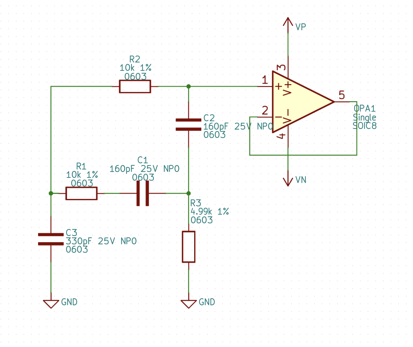

Symbols, placement, and the details that matter
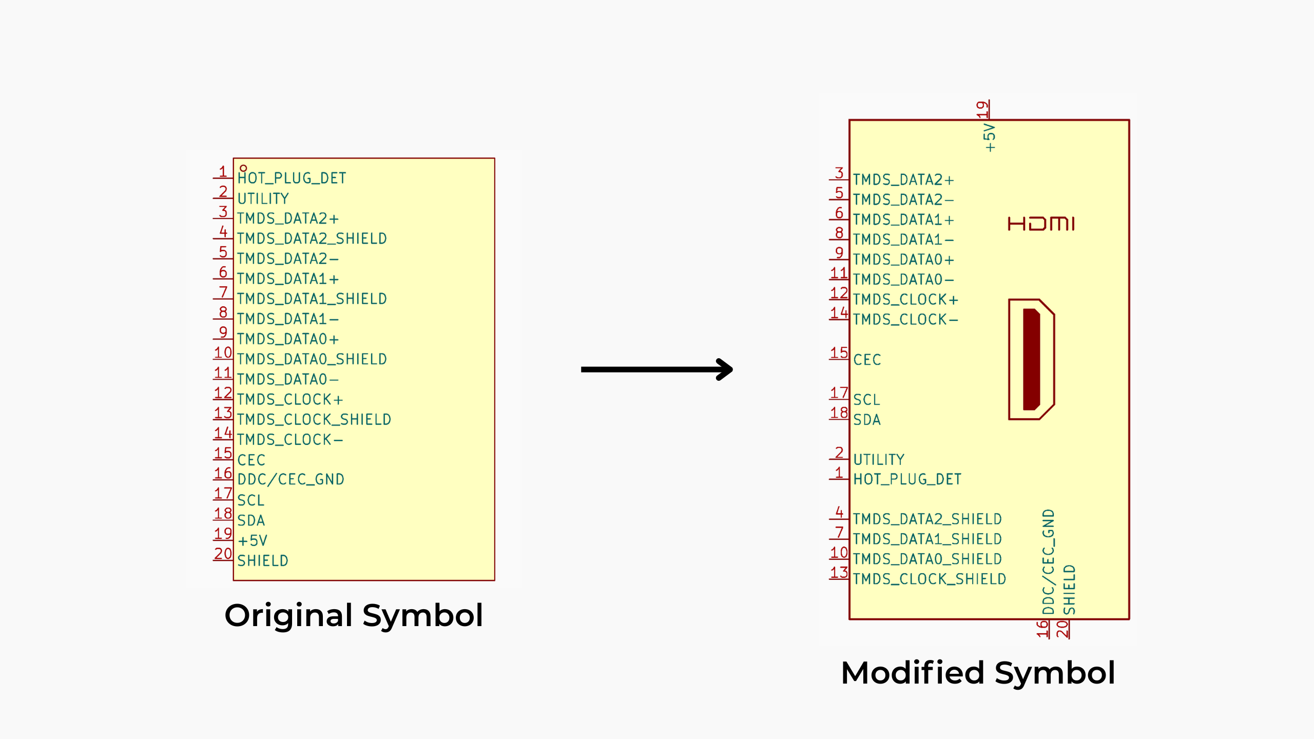
Beyond reference designs and firmware, we have found a number of smaller but meaningful ways to involve models in day to day PCB work. Symbol and footprint quality is a good example. There is an entire ecosystem of companies focused purely on ECAD libraries for a reason. Good symbols and footprints are essential if schematics are to remain readable as designs scale. Much of the internet’s KiCad library content is electrically correct but stylistically inconsistent. With Claude in the loop, we can describe the standards we want in natural language and have the model iteratively reshape downloaded symbols to match our conventions. It adjusts pin ordering, groups related functions, and cleans up graphics so design reviews are faster and schematics are easier to scan.